
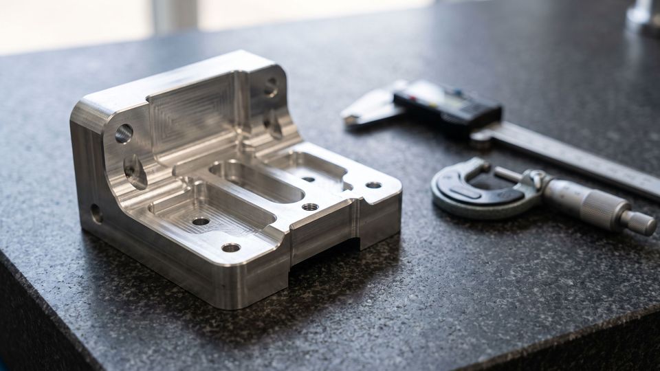
ISO 2768 sets the default tolerance for every dimension on a drawing that doesn’t carry its own. Put “ISO 2768-m” in the title block and a 50mm untoleranced dimension may vary by ±0.3mm, a 10mm one by ±0.2mm, and so on across the size ranges in the standard’s tables.
The “K” in the familiar “ISO 2768-mK” points to ISO 2768-2, which was withdrawn in 2021. And ISO 2768-1 itself is being replaced by a new edition that ISO lists as under publication right now.
ISO 2768 general tolerances are common on drawings for both CNC milling and CNC turning work. This guide gives you the tables, explains what the current changes mean for drawings already in circulation, and covers the point where a general tolerance stops being enough.
What ISO 2768 Does on a Drawing
ISO 2768 is a general tolerance standard. One note near the title block gives every untoleranced linear and angular dimension a permissible deviation, picked from a table by class (f, m, c or v) and by the size of the dimension.
It saves a designer from tolerancing every chamfer, pocket depth and outside edge individually. It also stops the person at the machine from guessing.
General tolerances do not apply to dimensions shown in brackets (auxiliary dimensions), dimensions in rectangular frames (theoretically exact dimensions used with geometric tolerancing), or anything that carries its own individual tolerance.
ISO 2768-1 Linear Tolerance Table
This is the table most people are looking for. Values are permissible deviations in millimetres.
| Nominal size (mm) | f (fine) | m (medium) | c (coarse) | v (very coarse) |
|---|---|---|---|---|
| 0.5 up to 3 | ±0.05 | ±0.1 | ±0.2 | n/a |
| Over 3 up to 6 | ±0.05 | ±0.1 | ±0.3 | ±0.5 |
| Over 6 up to 30 | ±0.1 | ±0.2 | ±0.5 | ±1 |
| Over 30 up to 120 | ±0.15 | ±0.3 | ±0.8 | ±1.5 |
| Over 120 up to 400 | ±0.2 | ±0.5 | ±1.2 | ±2.5 |
| Over 400 up to 1000 | ±0.3 | ±0.8 | ±2 | ±4 |
| Over 1000 up to 2000 | ±0.5 | ±1.2 | ±3 | ±6 |
| Over 2000 up to 4000 | n/a | ±2 | ±4 | ±8 |
So a 100mm length toleranced to ISO 2768-m can measure anywhere from 99.7mm to 100.3mm. To fine class, the same length must sit between 99.85mm and 100.15mm.
Below 0.5mm the standard doesn’t apply, and any tolerance has to be written next to the dimension.
Radii, Chamfers and Angles
Broken edges get their own, looser table. Fine and medium share values, as do coarse and very coarse.
| External radius or chamfer height (mm) | f and m | c and v |
|---|---|---|
| 0.5 up to 3 | ±0.2 | ±0.4 |
| Over 3 up to 6 | ±0.5 | ±1 |
| Over 6 | ±1 | ±2 |
Angular tolerances are chosen by the length of the shorter side of the angle, not by the size of the angle. A 90° corner between a 200mm face and a 15mm face is read on the “over 10 up to 50” row.
| Shorter side (mm) | f and m | c | v |
|---|---|---|---|
| Up to 10 | ±1° | ±1°30′ | ±3° |
| Over 10 up to 50 | ±0°30′ | ±1° | ±2° |
| Over 50 up to 120 | ±0°20′ | ±0°30′ | ±1° |
| Over 120 up to 400 | ±0°10′ | ±0°15′ | ±0°30′ |
| Over 400 | ±0°5′ | ±0°10′ | ±0°20′ |
What ISO 2768-mK Means, and Why the K Is Out of Date
The lowercase letter is the ISO 2768-1 class for sizes and angles. The uppercase letter is the ISO 2768-2 class for general geometrical tolerances, which came in three grades: H (tightest), K and L.
ISO 2768-mK therefore means medium tolerances on sizes and angles, plus class K for straightness, flatness, perpendicularity, symmetry and run-out.
| Characteristic | H | K | L |
|---|---|---|---|
| Straightness and flatness, over 30 up to 100mm | 0.1 | 0.2 | 0.4 |
| Straightness and flatness, over 100 up to 300mm | 0.2 | 0.4 | 0.8 |
| Perpendicularity, shorter side up to 100mm | 0.2 | 0.4 | 0.6 |
| Circular run-out (any size) | 0.1 | 0.2 | 0.5 |
These rows are a sample. Part 2 had full tables for each characteristic across length ranges.
Here is the catch. ISO 2768-2:1989 was withdrawn in February 2021 and replaced by ISO 22081:2021, which drops the H, K and L classes entirely in favour of a general geometrical specification tied to a datum system.
What that means for drawings in circulation
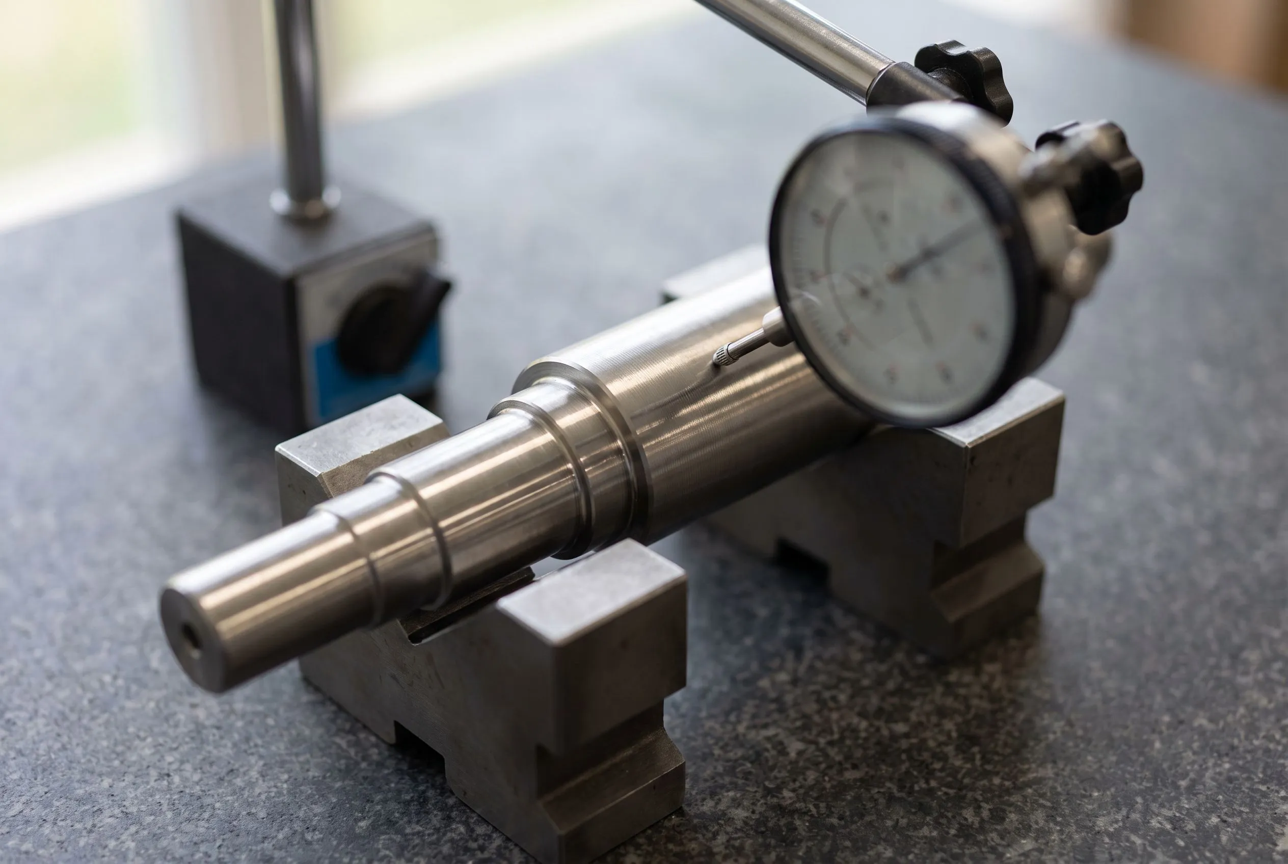
A drawing that says ISO 2768-mK is still a valid instruction. The drawing is the contract, and the withdrawal of part 2 doesn’t change what the designer asked for when it was issued.
The values above still apply to those drawings unless the customer and supplier agree a change. For new drawings, designers working to current ISO practice should replace the K with a general geometrical specification to ISO 22081, or put individual geometric tolerances on the features that matter.
The New Edition of ISO 2768
ISO is replacing ISO 2768-1:1989 with a single-part second edition of ISO 2768. It is listed at stage 60.00, “International Standard under publication”, with a publication date of October 2026.
Its new title tells you where it is heading: “Geometrical product specifications (GPS), Dimensional tolerancing, Tolerance limits for general specification of linear and angular sizes”. That brings it into the same GPS family as ISO 22081.
The full text is not freely available yet, so we won’t guess at the detailed changes. Two things are safe to say now:
- Existing drawings don’t change. A drawing referencing ISO 2768-1 means what it meant on the day it was issued.
- New drawings should state the edition once the new standard is published, so supplier and customer read the same tables.
Which Class Should You Put on Your Drawing?
ISO 2768-1 itself says the class should be chosen with the workshop’s “customary accuracy” in mind. In practice, that points most machined parts towards medium.
- f (fine) suits small, precise components where untoleranced features still affect fit or appearance, such as instrument parts and small turned pins.
- m (medium) is the sensible default for CNC machined parts. On modern machining centres and lathes it sits comfortably inside normal process capability.
- c (coarse) and v (very coarse) suit fabrications, sheet metal and rough-machined castings, and are rarely the right call for precision-machined work.
Machined plastics need more thought, because they move with temperature far more than metals do. Our Delrin machining page covers the tolerances that are realistic on acetal parts.
Choosing f over m “to be safe” rarely buys anything on a small part, and on large parts it can add real cost. Over 400mm, fine class means ±0.3mm instead of ±0.8mm across every untoleranced dimension, and that has to be held, measured and recorded on first article inspection.
What drives price is not usually the general class. It is the individual tolerances tighter than the general class allows, and the inspection that goes with them, as our UK CNC machining cost guide explains.
When ISO 2768 Isn’t Enough
General tolerances are for features that don’t matter much. Anything that has to fit, seal, locate or run true needs its own tolerance.
Bores for bearings and dowels are the classic example. A 20mm hole toleranced H7 to ISO 286 must measure between 20.000mm and 20.021mm, a band of 0.021mm.
The same hole left to ISO 2768-f could measure anywhere from 19.9mm to 20.1mm, a band of 0.2mm. That is almost ten times looser, and a bearing would either fall through it or never go in.
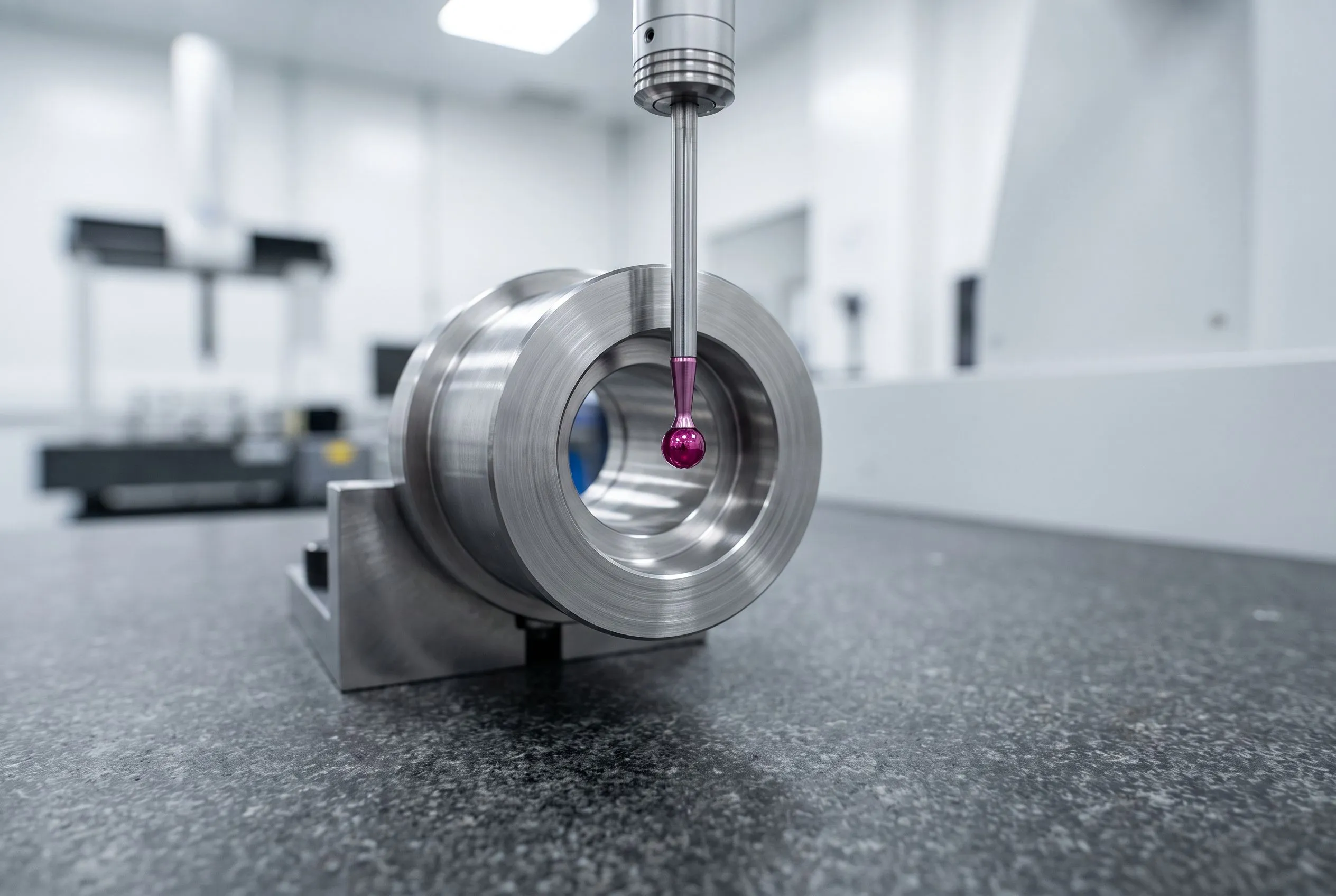
A good rule of thumb when reviewing a drawing: if a feature mates with another part, it should have an individual tolerance or a fit, and if position relative to other features matters, it should have geometric tolerancing. We hold ±0.01mm on critical features and verify them on the CMM in our temperature-controlled inspection department.
Is a Part Rejected If It’s Outside the General Tolerance?
Not automatically. ISO 2768-1 states that a workpiece exceeding a general tolerance should only lead to rejection if its ability to function is impaired.
That clause is less useful than it sounds. Most customers’ quality systems treat any out-of-tolerance dimension as a nonconformance, and a good supplier will report it rather than decide on your behalf whether it matters.
If a dimension genuinely doesn’t matter, the better fix is on the drawing. Give it a coarser class or a note, so nobody has to argue about it later.
Getting ISO 2768 Parts Quoted
Send the drawing with the 3D model if you have one. If anything is ambiguous, such as which edition of a standard applies or a feature that looks like it needs a fit, mention it with your enquiry so it can be settled before quoting.
For one-offs and development parts, our prototype machining service works from the same drawings, so the same drawing and inspection plan carry through to production.
Frequently Asked Questions
What does ISO 2768-mK mean?
ISO 2768-mK means medium (m) general tolerances for linear and angular dimensions from ISO 2768-1, combined with class K general geometrical tolerances from ISO 2768-2. Part 2 was withdrawn in 2021 and replaced by ISO 22081, but drawings issued with mK are still valid instructions and those values still apply.
What is the ISO 2768-m tolerance for a 100mm dimension?
±0.3mm. A 100mm nominal size falls in the over 30 up to 120mm range, where medium class gives ±0.3mm. In the same range, fine class gives ±0.15mm and coarse class gives ±0.8mm.
Is ISO 2768 still valid?
Partly. ISO 2768-1:1989 is still a published standard, but ISO lists a second edition of ISO 2768 as under publication, due to replace it. ISO 2768-2:1989 was withdrawn in February 2021 and replaced by ISO 22081:2021. Existing drawings that reference either part remain valid instructions.
What is the difference between ISO 2768 f and m?
Fine (f) roughly halves the medium (m) tolerance in most size ranges. For a dimension between 30 and 120mm, f allows ±0.15mm and m allows ±0.3mm. Medium is the usual default for machined parts, while fine suits small precise components where the extra control is genuinely needed.
Does ISO 2768 apply to plastic parts?
It can. ISO 2768-1 was written for parts made by metal removal or formed from sheet metal, but notes its tolerances may suit other materials. Machined plastics move more with temperature and, for nylon, moisture, so fine class on large plastic parts can be hard to hold and check consistently.